Hardware Assembly
Now that we're familiar with the INA2XX sensors and other hardware on these boards, it's time to assemble a simple circuit to measure power consumed by a single LED. If you're not familiar with using a breadboard or wiring LEDs and other power circuits, you may want to check out these tutorials before proceeding:
Basic LED Demo Assembly
We'll start by assembling our LED or Load circuit on the breadboard.
First, plug the LED into the breadboard along a single column. Next, connect one side of the resistor to the cathode (-) pin of the LED and the other side of the resistor to the breadboard's ground rail.
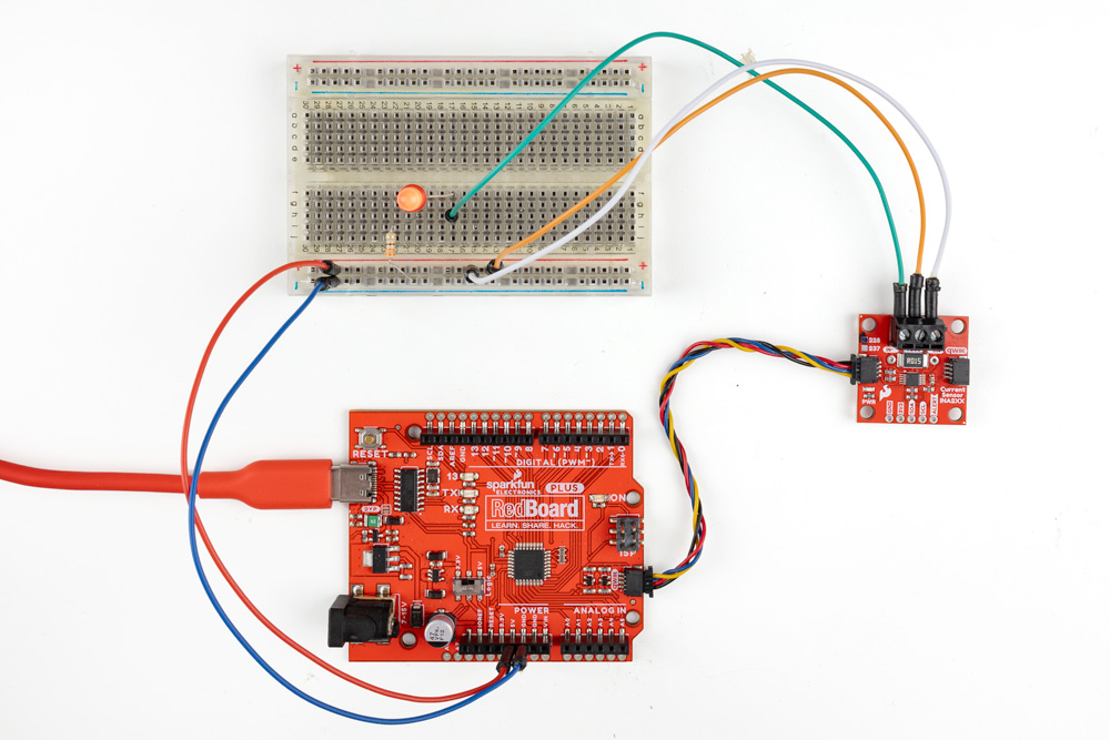
Now take three jumper wires and secure them to the 3-pin screw terminal on the Current Sensor - INA2XX breakout. If you're referencing the photo below, the wire colors for the screw terminal pins are:
- IN+ - White
- VBUS - Orange
- IN- - Green
Connect the IN+ (White) and VBUS (Orange) wires to the + rail on the breadboard and connect the IN- (Green) wire to the same row on the breadboard as the LED's anode (+) pin.
Now that our LED is wired up to the current sensor, we'll need to wire the RedBoard's power pins to the breadboard to power the LED. Connect the RedBoard's 3.3V output to the + rail on the breadboard (the Red wire in the photo below) and one of the RedBoard's ground pins to the "-" rail on the breadboard (the Blue wire in the photo below).
With the breadboard circuit complete, we can now connect the Current Sensor - INA2XX to the RedBoard using a Qwiic cable and finally plug the RedBoard into a computer using a USB-C cable. The completed circuit should look similar to the photo below:
Now that we have a complete demo circuit, we can move on to installing and using the SparkFun INA2XX Arduino library and the examples included in it.